Quadrilateralized Spherical Cube
Classification |
Azimuthal |
Available forms |
Forward and inverse, ellipsoidal |
Defined area |
Global |
Alias |
qsc |
Domain |
2D |
Input type |
Geodetic coordinates |
Output type |
Projected coordinates |
The purpose of the Quadrilateralized Spherical Cube (QSC) projection is to project a sphere surface onto the six sides of a cube:
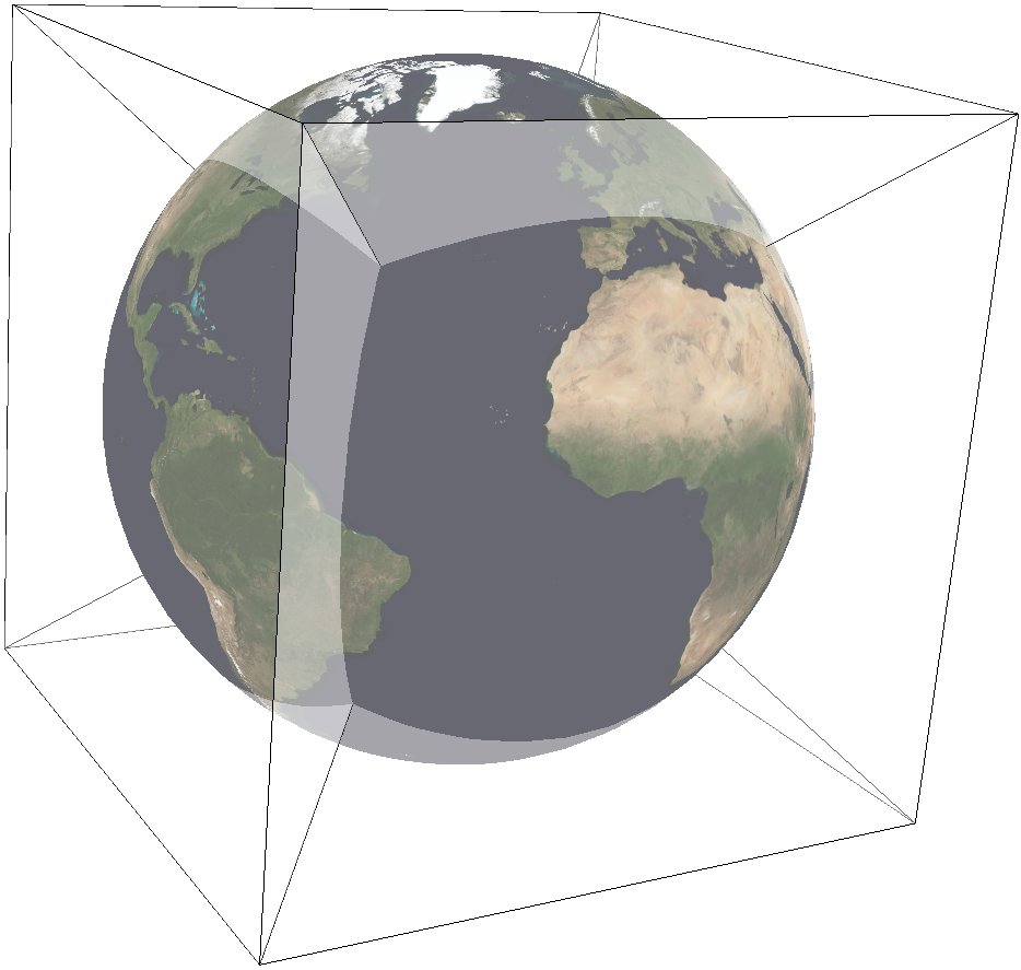
For this purpose, other alternatives can be used, notably Gnomonic or HEALPix. However, QSC projection has the following favorable properties:
It is an equal-area projection, and at the same time introduces only limited angular distortions. It treats all cube sides equally, i.e. it does not use different projections for polar areas and equatorial areas. These properties make QSC projection a good choice for planetary-scale terrain rendering. Map data can be organized in quadtree structures for each cube side. See [LambersKolb2012] for an example.
The QSC projection was introduced by [ONeilLaubscher1976], building on previous work by [ChanONeil1975]. For clarity: The earlier QSC variant described in [ChanONeil1975] became known as the COBE QSC since it was used by the NASA Cosmic Background Explorer (COBE) project; it is an approximately equal-area projection and is not the same as the QSC projection.
See also [CalabrettaGreisen2002] Sec. 5.6.2 and 5.6.3 for a description of both and some analysis.
In this implementation, the QSC projection projects onto one side of a circumscribed cube. The cube side is selected by choosing one of the following six projection centers:
|
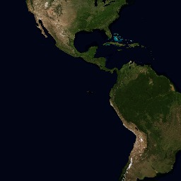
front cube side |
|
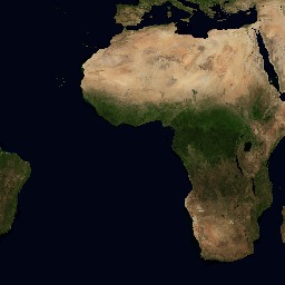
right cube side |
|
back cube side |
|
left cube side |
|
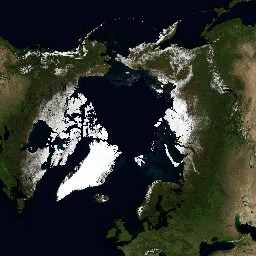
top cube side |
|
bottom cube side |
Furthermore, this implementation allows the projection to be applied to ellipsoids. A preceding shift to a sphere is performed automatically; see [LambersKolb2012] for details.
Usage
The following example uses QSC projection via GDAL to create the six cube side maps from a world map for the WGS84 ellipsoid:
gdalwarp -t_srs "+wktext +proj=qsc +units=m +ellps=WGS84  +lat_0=0 +lon_0=0"        \
    -wo SOURCE_EXTRA=100 -wo SAMPLE_GRID=YES -te -6378137 -6378137 6378137 6378137  \
    worldmap.tiff frontside.tiff

gdalwarp -t_srs "+wktext +proj=qsc +units=m +ellps=WGS84 +lat_0=0 +lon_0=90"        \
    -wo SOURCE_EXTRA=100 -wo SAMPLE_GRID=YES -te -6378137 -6378137 6378137 6378137  \
    worldmap.tiff rightside.tiff

gdalwarp -t_srs "+wktext +proj=qsc +units=m +ellps=WGS84 +lat_0=0 +lon_0=180"       \
    -wo SOURCE_EXTRA=100 -wo SAMPLE_GRID=YES -te -6378137 -6378137 6378137 6378137  \
    worldmap.tiff backside.tiff

gdalwarp -t_srs "+wktext +proj=qsc +units=m +ellps=WGS84 +lat_0=0 +lon_0=-90"       \
    -wo SOURCE_EXTRA=100 -wo SAMPLE_GRID=YES -te -6378137 -6378137 6378137 6378137  \
    worldmap.tiff leftside.tiff

gdalwarp -t_srs "+wktext +proj=qsc +units=m +ellps=WGS84 +lat_0=90 +lon_0=0"        \
    -wo SOURCE_EXTRA=100 -wo SAMPLE_GRID=YES -te -6378137 -6378137 6378137 6378137  \
    worldmap.tiff topside.tiff

gdalwarp -t_srs "+wktext +proj=qsc +units=m +ellps=WGS84 +lat_0=-90 +lon_0=0"       \
    -wo SOURCE_EXTRA=100 -wo SAMPLE_GRID=YES -te -6378137 -6378137 6378137 6378137  \
    worldmap.tiff bottomside.tiff
Explanation:
QSC projection is selected with
+wktext +proj=qsc.The WGS84 ellipsoid is specified with
+ellps=WGS84.The cube side is selected with
+lat_0=... +lon_0=....The
-wooptions are necessary for GDAL to avoid holes in the output maps.The
-teoption limits the extends of the output map to the major axis diameter (from -radius to +radius in both x and y direction). These are the dimensions of one side of the circumscribing cube.
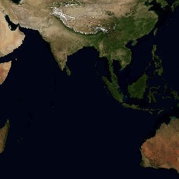
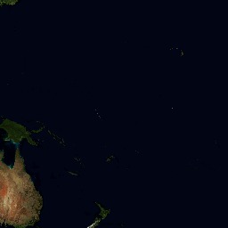
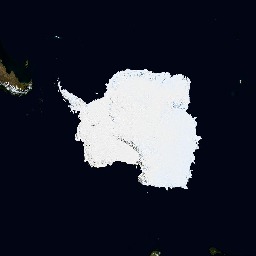
The resulting images can be laid out in a grid like below.
|
|||
|
|
|
|
|
Parameters
Note
All parameters for the projection are optional.
- +lon_0=<value>
Longitude of projection center.
Defaults to 0.0.
Note
The default convention is to interpret this value as decimal degrees. To specify radians instead, follow the value with the "r" character.
Example: +lon_0=1.570796r
See Projection Units for more information.
- +lat_0=<value>
Latitude of projection center.
Defaults to 0.0.
Note
The default convention is to interpret this value as decimal degrees. To specify radians instead, follow the value with the "r" character.
Example: +lat_0=1.570796r
See Projection Units for more information.
- +ellps=<value>
The name of a built-in ellipsoid definition.
See Ellipsoids for more information, or execute
proj -lefor a list of built-in ellipsoid names.Defaults to "GRS80".
- +x_0=<value>
False easting.
Defaults to 0.0.
- +y_0=<value>
False northing.
Defaults to 0.0.